|
|
|
|
News The Project Technology RoboSpatium Contribute Subject index Download Responses Games Gadgets Contact Rover - constructionRead how to control the roverDrive the rover The video about the construction detailsParts list
Parts list infrared interface
Rover 1.0Components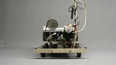
The decision to build a rover was a spontaneous idea which is why the vehicle was built by using materials being in my personal stock. Only a webcam had to be purchased to create the base car. Some later two LED flashlights were bought to upgrade the lighting. Originally I used a 10W halogen bulb as light beam which was too inefficient and four blue LEDs from the computer ventilator mentioned below 1(who the hell needs a illuminated computer ventilator?!?). The chassis was made of an old computer housing. Originally I used the wheels of an old toy tractor, but they were too old and so I replaced them with wheels used for RC model planes. The bumpers are made of aluminum bars which came from an old, tiny greenhouse. 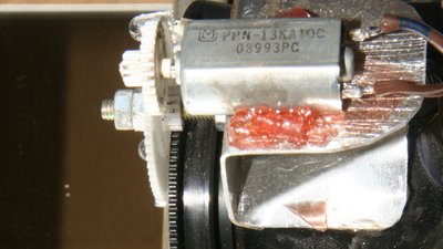
The webcam is a Logitech C160 with a resolution of 640x480 pixel. The manual focus is actuated by the motor and the gearwheels of an old CD Rom drive and two micro switches of a computer mouse act as sensors. The approximate dimensions of the rover are: 28x24x15cm (LxWxH) + 35cm hight for the power pole. 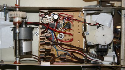
The engine of the rover is a geared motor with a nominal voltage of 12V, which is connected to 5V. The flange-mounted gear causes a speed reduction of 1:30 and together with the pinion at the gear (10 teeth) and the gearwheel at the drive shaft (30 teeth), there is a total reduction of 1:90. The steering is done by a S21 type standard servo. The connection to the "host computer" is done with the help of an ATMEGA8-16PU microcontroller 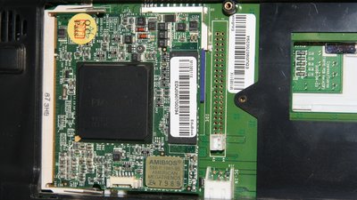
The "host computer" is an Edubook of the Norhtec company, which is a tiny laptop with a 8.9 inch display, running the Linux distribution KNOPPIX 6.2. The main processor is a Xcore86 CPU running with a speed of 1GHz and 512MB of RAM are soldered together with all components on the very tiny board. No Supercomputer, but there is no need for a brightly colored wish and wush 3D desktop. The most efficient programming work runs in a commandline! 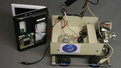
Some cooling for the fanless netbook is done by a ventilator, because there are sometimes tropical temperatures at the target area. Moreover the Edubook I own is a preproduction model which is heating up stronger while operating. The radio communication is done by a USB stick at the power pole of the rover. Two more USB interfaces are used by the webcam and the control board. 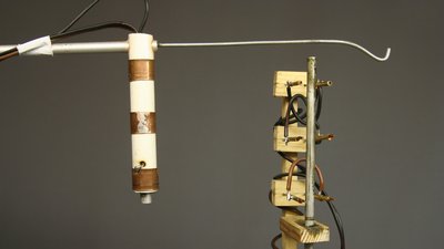
Instead of rechargeable batteries I am using the power supply of an old computer as the voltage source. I don't want to climb through the "stargate" every day to replace the battery packs. The Edubook needs 12V and the control board 5V with what three cables are running to the rover. To avoid the rover from getting tangled up in it's own cabling, the cords are running to the power pole at the top of the vehicle equipped with a anti-twist-mechanism. A couter weight can be put on the hook at the front of the mechanism. 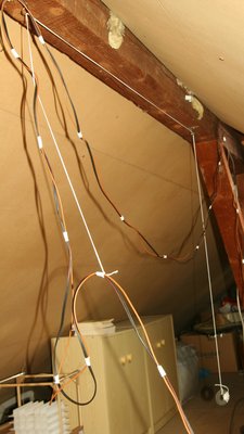
The cables are tightened with the help of a deflection roller fixed at a ceiling beam and a counter weight. While using another host computer like the Open Source solution "Pandaboard", which operates with a voltage supply of 5V, two cables would be sufficient. Rover 2.0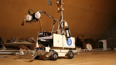
Meanwhile the Rover is equipped with a full HD webcam (Logitech C910). This camera has an automatic focus, which is why the manual focusing has been removed. The camera is now fixed at a pivotable lever so it can be lifted. The lever is actuated by a winch, which is turned by a servo. Furthermore the view angle of the camera can be altered by another servo. The illumination has been updated, too. There are 38 white LEDs attached to the camera, which can be dimmed by pulse width modulation. 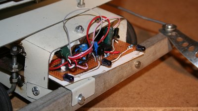
At the front side of the Rover there is another innovation - an infrared interface. It has a receiver modul as well as infrared diodes to be able to send and receive signals. Those interface is used to communicate with other microcontrollers. Inside the RoboSpatium there are certain modules (globe, turntable, laptop) which can be controlled via the interface. ElectronicsControl board and Edubook are connected via an USB interface which is implemented by an Amega8-16PU and the V-USB firmware of Objective Development. The microcontroller actuates the peripheral devices by a H bridge (drive motor forward / backward), three Servos (left / right, camera arm) and one power transistor (light). The part list was ruled by the devices inside of my personal "warehouse".
The H-bridge used to control the drive motor is not perfect. The transistors BD649/650 could be operated with a continuous current up to 8A under normal conditions. The transistors are not switched correctly when using the configuration drawn at this circuit, but the arrangement is good enough to operate the rover motor, which consumes just 400mA while blocked. The base of the transistor switching the LEDs is connected to the microcontroller via a series resistor. The current running through the LEDs is approximately 100mA. Choose another configuration if you intend to build a stronger powered or illuminated vehicle. The 38kHz oscillator circuit used to switch the infrared diodes, is implemented with the help of an operational amplifier type MC34074P. The output signal is not a perfect rectangle signal, but the range of the infrared interface is more than sufficient. Control softwareA mix of Java script (webpage), Perl scripts (communication between rover and the server of my Internet provider) and C programs (USB interface between Edubook and microcontroller) is used to control the rover. The source code of the programs is available for download and I'd just like to explain the communication procedure between rover and Internet server. The network communication from rover to router (WLAN + dLAN) and from router to Internet server could be interrupted or delayed sometimes. That is why the operation of the Perl scripts is monitored permanently. Both "rover-client.perl", and "rover-server.perl" are instructed to write the current time in special files while they are running. Those timestamp is read by another Perl script. If the timestamp is older than 35 seconds, the monitoring script (watchdog-client.perl respectively watchdog-server.perl) kills and restarts the hanging script. If there are 5 restarts during 5 minutes, the watchdog script of the rover initiates a reboot of the operating system. At the rover, the network communication is additionally observed by another script which starts each 2minutes by a cron job. Those script sends 4 ping signals to the router and restarts the network if there is no answer. Rebooting procedures like that are often used at space probes, because the control software is complex, hence it is rarely free from bugs. The Perl scripts are also responsible for the transfer of the pictures from the webcam to the Internet server. Controlled by Javascript, the picture inside of your browser is updated after 2 seconds. The advantage of this method is that there is no plugin necessary to control the rover.Besides the webpage, the files "rover-server.perl", "watchdog-server.perl" and "rover-status.pl" are stored at the server. Those Internet Server has to permit the execution of Perl scripts! The files "rover-client.perl", "watchdog-client.perl", "roverControl" and "rover-client-commands.perl" are stored at the hard disk of the rover and the file "main.hex" has to be inside the memory of the microcontroller. Some more questions about the rover?You can find my mail address at the column ImprintNews The Project Technology RoboSpatium Contribute Subject index Archives Download Responses Games Links Gadgets Contact Imprint |
|
|