|
|
|
|
News The Project Technology RoboSpatium Contribute Subject index Download Responses Games Gadgets Contact <<< EDM: Plasma properties EDM: Wagners Hammer (1) >>> EDM: Electronics, introductionThe first video about the electronics of my EDM machine
You can buy the Andonstar AS246 microscope on: Step-Up converter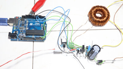
In this EDM chapter, I want to take a closer look at the electronics and address key points for future improvements. As shown in the first chapter, the circuit is the rustic version of a boost converter with the components joined via copper wires. The circuit is fed by the 12V line of an old computer power supply and an output voltage of up to 40V is generated by the main components. 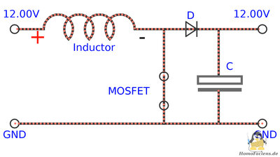
The coil is connected in parallel to the input voltage and so gets "charged" when the MOSFET is turned ON ... 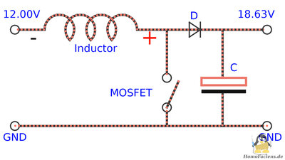
...and the inductor gets "discharged" when the MOSFET is turned OFF. The induction voltage generated by the coil is now added to the input voltage and thus charges the capacitor via a diode to a voltage higher than the input voltage. This cycle is repeated several times until the desired output voltage is reached. A microcontroller type ATmega328 is switching the MOSFET and monitors the output voltage accross the capacitor. 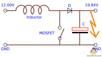
Once the capacitor has been charged to the specified voltage, a "shot" for spark erosion can take place: Changing the capacitance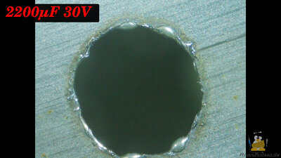
For the first drilling I leaft the circuit as in the previous chapters with the output voltage set to 30V. After a total of 115 shots, the drilling process is finished. 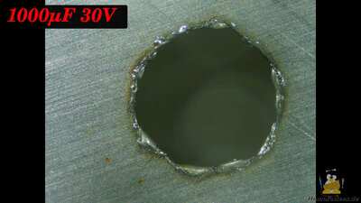
In previous chapters I already mentioned that less can be more. I therefore replaced the capacitor for this attempt with a smaller one with only 1000μF. With this component, the bore is completed after 156 shots, instead of the 115 shots with the capacitor, which is more than twice the size. 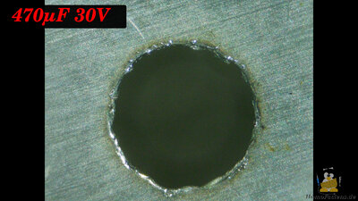
With a 470μF capacitor, 342 shots are needed. 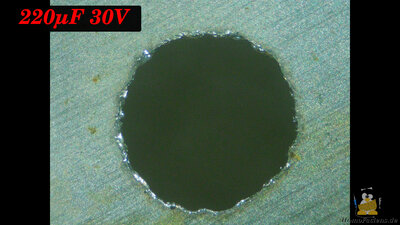
As the last capacitor, I use a 220μF device, which is just one tenth of the capacity used in the first experiment. With this, 503 shots are required for the bore, which is significantly less than ten times the shots required with the large capacitor - this also proves that when it comes to sparks, physics is not as straightforward as might be expected. At the finished hole, it can be seen that with the smaller capacitor, drops of resolidified metal have not formed as thick at the edges. Furthermore, the resulting hole is somewhat more circular. Chaning the polarity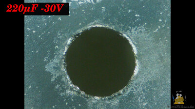
In the previous chapter I showed that sparks do not affect both electrodes in the same way. So let's change the polarity next: Now there is ground on the workpiece and the +30V line runs to the 1mm drill. 825 shots are now required for drilling, which is clearly more than with the original polarity. It can also be seen that the grooves on the metal surface of the razor blade are disappearing - light gray deposits are forming here. In addition to the sparks, redox reactions also contribute to the changes on the metal surface. If, as here, the workpiece forms the cathode, the excess of electrons cause that metal ions in the water get reduced to elementary metal, deposited on the surface. Steel does not only consist of iron and the water molecules also contribute to a whole series of redox reactions in the vat. The diameter of the finished hole is slightly smaller, but not because the spark gap is smaller,... 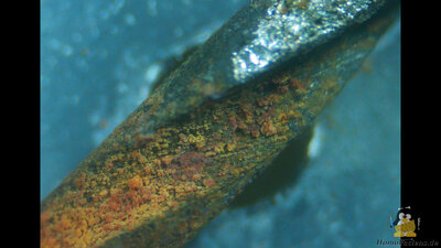
...but because the drill has become thinner. The iron oxidizes at the anode and so metal ions dissolve. These redox reactions do not take place in the plasma of the sparks, but on the entire surface of the drill that is immersed in the water - a rust-red layer can clearly be seen on the surface of the drill. There is a lot to tell about the problem of tool electrode erosion in upcoming chapters. Changing the voltage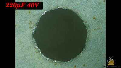
As the next parameter, let's increase the voltage with which the capacitor is charged to 40V. The energy stored in the capacitor increases squared with the voltage. With the 220μF capacitor now only 262 shots are needed to pierce the razor blade. 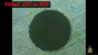
High energy per shot means more material is removed, but the resulting edges are less smooth. It takes longer with less energy, but the results are more precise. Anyone who can write software therefore has a clear advantage: In this experiment, the first 180 shots were made with a voltage of 40V to be able to drill quickly. Then the microcontroller switched to a voltage of only 20V, which makes the edges of the hole much smoother. After a total of 544 shots, this hole is the most precise so far. Rapid spark sequence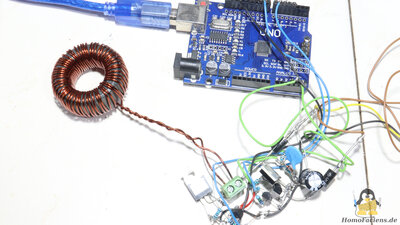
Since I paused the drilling process after each shot to take a photo with my microscope, the rate at which the capacitor charges was not important until now. In practice, however, one would like to generate as many sparks as possible per unit of time in order to be able to process a workpiece as quickly as possible. The rate at which a given capacitor is charged depends on the switching frequency and the inductance of the coil used. As a final modification, I now use a coil with fewer turns made of thicker enameled copper wire. This reduces the ohmic resistance and the inductance of the coil. With a base frequency of 8000Hz, this coil can be controlled in such a way that the MOSFET just doesn't end up in smoke. 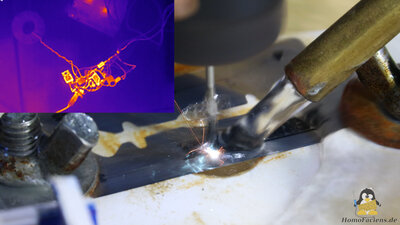
The thermal imaging camera makes the switching losses of my all too simple electronic design clearly visible - the MOSFETS are shining in bright colors. However, the coil stays completely cool, at least in this test run. 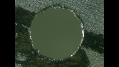
The target voltage of 40V is easily reached - the electrolytic capacitor cannot withstand a much higher voltage. With this setup, the bore is completed in just 60 seconds and 245 shots. <<< EDM: Plasma properties EDM: Wagners Hammer (1) >>> News The Project Technology RoboSpatium Contribute Subject index Archives Download Responses Games Links Gadgets Contact Imprint |
|
|